Basic ex:no:01
LED Interfacing - How To?
The world of LEDS
The Intensity can be varied by controlling the voltage applied to the individual pins. If you take a look at the 11th PIN on the arduino, you would see a marking 'PWM' next to it (Remember we connected our LED to the 11th pin). The PWM pins in addition to generating digital HIGH / LOW signals can generate analog voltages between 0 & 5.
The PWM Pins [Pins 3,5,6,9,10,11] that can generate a PWM signal of 8-bit resolution.[8-bits can represent a maximum value of 255, and a 8-bit resolution here means that 5 volts is represented by 255 divisions. So if you want to generate 1 volt, you would use the value 51]
The analogWrite function will take a 8-bit numerical value as a parameter [called duty cycle] and produce an output voltage corresponding to this value. It will set the pin to generate a steady square wave of the specified duty cycle at roughly 490Hz frequency.
Finally, when using a pin in the PWM mode, we don't have to use the pinMode() function.
Try the following code with the same setup and see how the intensity increases and decreases...[Intensity.ino]
LEDs (Light Emitting Diodes) are the
most commonly used of electronic components. They are everywhere –
torches, displays, indicators, etc. Every project will eventually end
up having atleast one led. The Official Arduino Boards and most of
the Clones do come with an on-board LED which you can try with the
default blink program found in the File->Examples->Basic menu
of Arduino IDE.
So How to Connect a LED?
The Long of the LED is the Anode (Positive Terminal!) and the short led is the Cathode(Negative Terminal).
 |
| The Terminals of the LED |
 |
| Place the LED as shown |
 |
| Place a Current Limiting Resistor (too much current passing through an LED can burn it!) between the negative terminal of the LED and the '-'ve terminal on the power rail (we will soon connect this to the '-'ve (aka ground) of our Arduino Board!) |
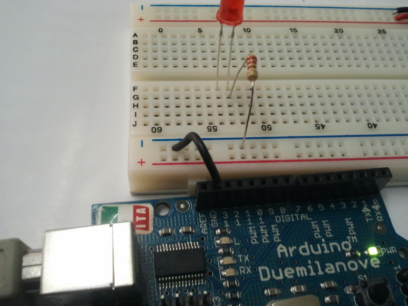 |
| Take a wire from the pin marked 'GND' of your arduino and connect it to the '-'ve power rail of the breadboard. Now all points of the '-' ve power rail will be connected to the ground of the arduino! |
 |
| Next, Connect a wire between the 11th pin of the arduino(yes the 11th pin and not the 13th pin!) and the positive terminal of the LED. This is going to be our control line for the LED |
Programming to control the LED
So
how can you control a LED? Well there are only 2 ways to control an
LED. you can either switch it ON / OFF or you can control the intensity
with which it glows (Very much like a fan!). So lets see how to do the
first control - ON/OFF (we can call this digital control! Very much 0s
& 1s)
Try the following code. [Blink.ino]
 /*
  Blink
  Turns on an LED on for one second, then off for one second, repeatedly.
  This example code is in the public domain.
  */
 void setup() {
  // initialize the digital pin as an output.
  // We have our LED connected to Pin 11
  pinMode(11, OUTPUT);     // Sets the 11th pin as an Output pin
 }
 void loop() {
  digitalWrite(11, HIGH);  // set the LED on
  delay(1000);       // wait for a second
  digitalWrite(11, LOW);  // set the LED off
  delay(1000);       // wait for a second
 }
Next, Lets see how to control the intensity of the LED.
The Intensity can be varied by controlling the voltage applied to the individual pins. If you take a look at the 11th PIN on the arduino, you would see a marking 'PWM' next to it (Remember we connected our LED to the 11th pin). The PWM pins in addition to generating digital HIGH / LOW signals can generate analog voltages between 0 & 5.
The PWM Pins [Pins 3,5,6,9,10,11] that can generate a PWM signal of 8-bit resolution.[8-bits can represent a maximum value of 255, and a 8-bit resolution here means that 5 volts is represented by 255 divisions. So if you want to generate 1 volt, you would use the value 51]
The analogWrite function will take a 8-bit numerical value as a parameter [called duty cycle] and produce an output voltage corresponding to this value. It will set the pin to generate a steady square wave of the specified duty cycle at roughly 490Hz frequency.
Finally, when using a pin in the PWM mode, we don't have to use the pinMode() function.
Try the following code with the same setup and see how the intensity increases and decreases...[Intensity.ino]
 /*
  Intensity
  Increases the Intensity of a LED from 0 to maximum and on reaching maximum
  starts decreasing back to 0
  */

 int intensity = 0;

 void setup() {

 }
 void loop() {

   while(intensity < 255) // Check if intensity has reached maximum value, if yes then exit the loop
   {
     analogWrite(11,intensity);
     delay(25);
     intensity++;
   }

   while(intensity > 0) // Check if intensity has reached minimum value, if yes then exit the loop
   {
     analogWrite(11,intensity);
     delay(25);
     intensity--;
   }

 }


No comments:
Post a Comment